Solar Hot Water Systems

A typical solar water heating system incorporates a solar collector, circulation pump, storage tank, controller, piping and various valves. There are many different configurations possible, the choice of design will depend on the purpose of the system, climate, space limitations and many other factors. Lets start by having a look at the basic kinds of systems configurations.
Active vs Passive Flow
A solar thermal system can be active or passive. This term relates to the movement of the heat transfer liquid through the solar collector. Passive systems rely on thermosiphoning action to slowly move the water through the collector. Active systems utilise a circulation pump to move the liquid. This page focuses on active systems as most Apricus collectors will be installed in this format.
Direct, Closed Loop & Drainback
There are three main categories of plumbing format for solar thermal systems.
- Direct
- Closed Loop (aka Indirect)
- Drainback
Let’s review each one by one, with a summary overview at the end of this page:
Direct System
Suitable For
- Moderate climates (winter night temperatures > -10oC / 50oF)
- Low water hardness (mineral content), otherwise scale will form in the collector
- Domestic or commercial applications
Design Details
- In a direct open flow system, the potable water is circulated directly through the collector. No glycol (anti-freeze) is used in the system.
- Mild freeze protection is provided in the form of pump circulation when the collector temperature approaches freezing temperatures.
- All system components in contact with the water must be potable water rated. Apricus AP solar collectors are suitable for direct flow systems having passed NSF-61 (USA) and Watermark (Australia) testing.
Advantages
- Efficient heat transfer as no heat exchangers are required.
- Allows simple retrofitting of existing hot water tank.
Disadvantages
- Not normally suitable for very cold areas. (certain system designs may allow direct flow to work in cold climates)
- Not suitable for areas with particularly hard water as limescale will form in the solar collector.
System Diagram Example
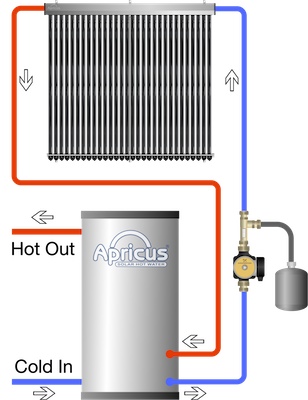
Below is an example of a direct flow system. This system has a mid mounted electric element, so the tank is accepting both solar input (bottom) while the top half of the tank is boosted as required (or with timer) to ensure hot water supply. This kind of system is suitable when there is not sufficient space for a dedicated solar pre-heat tank, or if the tank is large capacity.
The water is drawn directly from the bottom of the tank, through the collector and returned to a position about 1/4 the height of the tank.
Closed Loop
Suitable For
- Cold climates with winter night temperatures < -10oC / 50oF
- Poor water quality that would cause corrosion of the copper, or scale formation in the collector.
- Domestic or commercial applications
- Commercial applications when final liquid to be heated is not potable water.
Design Details
- The liquid circulated through the collector is separate from the water in the main hot water system
- The liquid can be plain water, or a glycol-water mix for areas that need freeze protection.
- The heat transfer between the closed loop and main system water is achieved via a heat exchanger, either internal coil inside the storage tank, or external heat exchanger.
Advantages
- Design to withstand freezing temperatures
- Can protect solar collect from scale in areas with poor water quality.
- Suitable for commercial style applications such as spas, pool heating, industrial heating etc.
- Can withstand stagnating conditions without heat dissipation if designed for steamback operation (Apricus evacuated tube collector are suitable for steamback operation).
Disadvantages
- Not as efficient as direct flow system, due to the need to use a heat exchanger
- In cold regions, anti-freeze liquid must be inspected and changed periodically (every 2-5 years). Warm regions can just use water.
- System cost is higher due to need for:
- Heat transfer fluid (normally propylene glycol based anti-freeze)
- More complex pump station (fill & drain valves, pressure relief valve, air separator etc)
System Diagram Example
Below are examples of two indirect systems, on the left with a coil heat exchanger, on the right using an external heat exchanger.
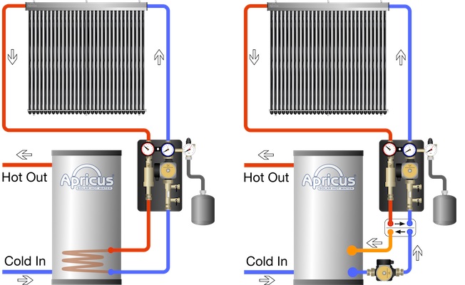
A coil heat exchanger is normally the best choice for domestic applications. An external heat exchanger may be chosen for a domestic application if the existing tank is to be used, thus avoiding the need to purchase a dedicated tank. Commercial applications also commonly use an external heat exchanger as they can be easily sized to meet the heat exchange demands.
A disadvantage of an external heat exchanger is the need for a pump on the hot water tank side to circulate water through the heat exchanger whenever the solar pump is operational. This adds costs to the system and also additional electricity usage.
Drain back
Suitable For
- Cold climates with winter night temperatures < -10oC / 50oF
- Poor water quality that would cause corrosion of the copper, or scale formation in the collector.
- Commercial applications when final liquid to be heated is not potable water.
- System where overheating is a potential issue
- Domestic or commercial applications
Details
- Heat transfer liquid drain from the collector and flow and return lines whenever the pump is turned off, hence the name “drain back”.
- As the collector is empty when the pump is off, there is no water to freeze (when cold) or turn to steam (when hot).
- A high head pump is required to overcome the vertical lifting of water to the height of the collector.
- A small drainback tank is required with the water returning from the collector delivered above the water level, allowing air back up the line each time the pump turns off.
Advantages
- Prevents freezing issues, even during power outages.
- Prevents excessive heat related issues.
- Avoids the need for glycol-based heat transfer fluid.
Disadvantages
- Not as efficient as direct flow system, due to the need to use a heat exchanger.
- Piping collectors must be slightly sloped to facilitate complete drainage, this increases the requirement for the installation quality, and required straight hard metal pipe rather that flexible line sets or soft copper.
- A more expensive higher head pump is required which may use 2-4 times as much electricity as a direct or indirect circulation pump for equivalent number of collectors and pipe run length.
System Diagram Example
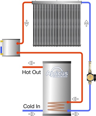
Below is a simple drain back system diagram, showing the small drainback tank. The heat exchanger can be either a coil in the drainback tank, coil in the main tank or an external heat exchanger (for commercial projects). Note the simplicity of the “plumbing” equipment. All that is required is a circualation pump and check valve plus some isolation and drain valves.
Summary
Which is the best system? Which is the best for a specific application?
Each system format has its advantages and disadvantages. Each can work very effectively and reliably if designed correctly and installed by an experienced contractor. The decision of which format is suitable is a decision for an experienced solar engineer to make after assessing the specifics of the application. Some solar engineers or installers strongly prefer a certain system format over another, based on years of experience. The advice in such a case is to listen to them! If in doubt about the suitability of the system design you can always contact for expert advice.
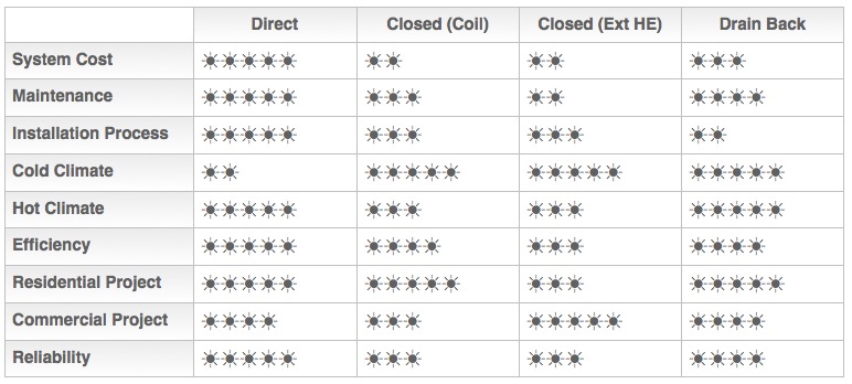
Here is a summary table of the 3 system formats:
